How to Measure DC Voltage Using Fluke Multimeter
A digital multimeter (DMM) is an essential tool for anyone involved in electronics. It measures voltage, current, resistance, continuity, and other parameters. The simplest and most common measurement to obtain using a multimeter is voltage. At the surface level, it’s a straightforward measurement, but a deeper understanding of this function can enhance the tool's value. Voltage is the potential difference between two points in a circuit, categorized as either AC (alternating current) or DC (direct current). AC flows in sine waves, while DC travels in a straight line in one direction only. This guide will walk you through measuring DC voltage using a Fluke multimeter and outline safety precautions to keep in mind.
Understanding DC Voltage Measurement
What is DC Voltage?
DC voltage, or direct current voltage, refers to the constant flow of electric charge in one direction. Unlike AC voltage, which alternates direction periodically, DC voltage remains constant, making it ideal for batteries and electronic devices.
Preparing for Measurement with Fluke Multimeter
To measure DC voltage using a Fluke multimeter:
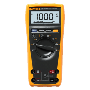
- Turn the Selector Dial: Set the dial to the DC Voltage setting. On some auto-ranging multimeters, there will only be one DC voltage selection, while others may have multiple options such as 2V, 20V, 200V, up to 1000V.
- Choose the Voltage Range: Start with the highest voltage range and adjust downwards to find the appropriate setting.
Step-by-Step Guide to Measuring DC Voltage
Step 1: Select DC Voltage Setting
Turn the selector dial on the multimeter to the DC voltage setting. For auto-ranging multimeters, choose the DC voltage option on the dial. For manual-ranging multimeters, start with the highest voltage setting and gradually lower it.
Step 2: Prepare the Circuit
Power off the circuit or wiring under test to avoid shorting out adjacent wires, terminals, or points with differing voltages.
Step 3: Connect the Probes
- Black Probe: Connect the black probe to the negative terminal of the battery and the COM connection on the multimeter.
- Red Probe: Connect the red probe to the positive terminal of the battery and the V connection on the multimeter. This connection may also be marked with other symbols like the ohm symbol.
Step 4: Measure the Voltage
- Place Probes: Touch the black probe against the first point of the circuit/wiring.
- Power Up: Power up the equipment.
- Take Reading: Touch the red probe against the second point of the test. Ensure you don’t bridge the gap between the point being tested and adjacent wiring, terminals, or tracks on a PCB. Read the voltage on the LCD display.
Handling Probe Reversal
If the red and black probes are connected incorrectly to the battery, the digital multimeter will display a negative sign next to the voltage. This reversal does not harm the multimeter but can damage an analog multimeter if the polarity is reversed.
Safety Precautions
Check Probes and Test Leads
Always inspect your probes and test leads. Never use damaged probes to measure voltages.
Use Meters with Proper Protection
For testing mains voltages, use a meter with at least CAT III or preferably CAT IV protection. These meters incorporate high rupturing capacity (HRC) fuses and other internal safety components that offer maximum protection against overloads and transients.
Avoid Meter Damage
A meter with inadequate protection can blow up and cause injury if connected incorrectly or if a transient voltage generates an internal arc.
Accurately measuring DC voltage using a Fluke multimeter involves selecting the correct settings, connecting the probes correctly, and following safety precautions. By adhering to these guidelines, you can ensure reliable measurements and maintain safety while working with electronic circuits.
Explore our range of Fluke multimeters to find the best tool for your needs
More Fluke's Interesting Articles